原文地址:http://www.ni.com/white-paper/11390/en/
Overview
This article explains the general concepts of the serial communication protocols RS-232, RS-422, and RS-485, including basic concepts like baud rate, data bits, stop bits, parity, and handshaking.
Table of Contents
- What is Serial?
- What is RS-232?
- What is RS-422?
- What Is RS-485?
- How do RS-232, RS-422, and RS-485 Compare?
- What is Handshaking?
- Related Links
1. What is Serial?
The concept of serial communication is simple. The serial port sends and receives bytes of information one bit at a time. This is slower than parallel communication, which allows the transmission of an entire byte at once; however, it is simpler and can be used over longer distances. For example, the IEEE 488 specifications for parallel communication state that the cabling between equipment can be no more than 20 meters total, with no more than 2 meters between any two devices; serial can extend as much as 1200 meters.
Typically, serial is used to transmit ASCII data. Communication is completed using 3 transmission lines: (1) Ground, (2) Transmit, and (3) Receive. Since serial is asynchronous, the port is able to transmit data on one line while receiving data on another. This is referred to as Full-Duplex transmission. Other lines are available for handshaking, but are not required. The important serial characteristics are baud rate, data bits, stop bits, and parity. For two ports to communicate, these parameters must match:
- Baud rate is a speed measurement for communication. It indicates the number of bit transfers per second. For example, 300 baud is 300 bits per second. When we refer to a clock cycle, in the context of serial, we mean the baud rate. For example, if the protocol calls for a 4800 baud rate, then the clock is running at 4800Hz. This means that the serial port is sampling the data line at 4800Hz. Common baud rates for telephone lines are 14400, 28800, and 33600. Baud rates greater than these are possible, but these rates reduce the distance by which devices can be separated. These high baud rates are used for device communication where the devices are located near one another.
- Data bits are a measurement of the actual data bits in a transmission. When the computer sends a packet of information, the amount of actual data may not be a full 8 bits. Standard values for the data packets are 5, 7, and 8 bits. Which setting you choose depends on what information you are transferring. For example, standard ASCII has values from 0 to 127 (7 bits). Extended ASCII uses 0 to 255 (8 bits). If the data being transferred is simple text (standard ASCII), then sending 7 bits of data per packet is sufficient for communication. A packet refers to a single byte transfer, including start/stop bits, data bits, and parity. Since the number of actual bits depend on the protocol selected, the term packet is used to cover all instances.
- Stop bits are used to signal the end of communication for a single packet. Typical values are 1, 1.5, and 2 bits. Since the data is clocked across the lines and each device has its own clock, it is possible for the two devices to become slightly out of sync. Therefore, the stop bits not only indicate the end of transmission but also give the computers some room for error in the clock speeds. The more bits that are used for stop bits, the greater the lenience in synchronizing the different clocks, but the slower the data transmission rate.
- Parity is a simple form of error checking that is used in serial communication. There are four types of parity: even, odd, marked, and spaced. The option of using no parity is also available. For even and odd parity, the serial port will set the parity bit (the last bit after the data bits) to a value to ensure that the transmission has an even or odd number of logic high bits. For example, if the data was 011, then for even parity, the parity bit would be 0 to keep the number of logic high bits even. If the parity was odd, then the parity bit would be 1, resulting in 3 logic high bits. Marked and spaced parity does not actually check the data bits, but simply sets the parity bit high for marked parity or low for spaced parity. This allows the receiving device to know the state of a bit which enables the device to determine if noise is corrupting the data or if the transmitting and receiving devices' clocks are out of sync.
2. What is RS-232?
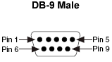
RS-232 (ANSI/EIA-232 Standard) is the serial connection historically found on IBM-compatible PCs. It is used for many purposes, such as connecting a mouse, printer, or modem, as well as industrial instrumentation. Because of improvements in line drivers and cables, applications often increase the performance of RS-232 beyond the distance and speed listed in the standard. RS-232 is limited to point-to-point connections between PC serial ports and devices. RS-232 hardware can be used for serial communication up to distances of 50 feet.

Data | |
TXD (pin 3) | Serial Data Output |
RXD (pin 2) | Serial Data Input |
Handshake | |
RTS (pin 7) | Request to Send |
CTS (pin 8) | Clear to Send |
DSR (pin 6) | Data Set Ready |
DCD (pin 1) | Data Carrier Detect |
DTR (pin 4) | Data Terminal Ready |
Ground | |
GND (pin 5) | Ground |
Other | |
RI (pin 9) | Ring Indicator |
Table 1: Pin Functions for RS-232
3. What is RS-422?
RS-422 (EIA RS-422-A Standard) is the serial connection historically used on Apple Macintosh computers. RS-422 uses a differential electrical signal, as opposed to unbalanced signals referenced to ground with the RS-232. Differential transmission uses two lines each for transmit and receive signals which results in greater noise immunity and longer distances as compared to the RS-232. These advantages make RS-422 a better fit for industrial applications.
4. What Is RS-485?
RS-485 (EIA-485 Standard) is an improvement over RS-422, because it increases the number of devices from 10 to 32 and defines the electrical characteristics necessary to ensure adequate signal voltages under maximum load. With this enhanced multi-drop capability, you can create networks of devices connected to a single RS-485 serial port. The noise immunity and multi-drop capability make RS-485 the serial connection of choice in industrial applications requiring many distributed devices networked to a PC or other controller for data collection, HMI, or other operations. RS-485 is a superset of RS-422; thus, all RS-422 devices may be controlled by RS-485. RS-485 hardware may be used for serial communication with up to 4000 feet of cable.
Data | |
TXD+ (pin 8) | Serial Data Output (differential) |
TXD- (pin 9) | Serial Data Output(differential) |
RXD+ (pin 4) | Serial Data Input(differential) |
RXD- (pin 5) | Serial Data Input(differential) |
Handshake | |
RTS+ (pin 3) | Request to Send (differential) |
RTS- (pin 7) | Request to Send (differential) |
CTS+ (pin 2) | Clear to Send (differential) |
CTS- (pin 6) | Clear to Send (differential) |
DSR (pin 6) | Data Set Ready |
Ground | |
GND (pin 1) | Ground |
Table 2: Pin Functions for RS-485 and RS-422
5. How do RS-232, RS-422, and RS-485 Compare?
RS-232 is the most common serial interface and used to ship as a standard component on most Windows-compatible desktop computers. Now it is more common to use RS-232 over USB using a converter. RS-232 only allows for one transmitter and one receiver on each line. RS-232 also uses a Full-Duplex transmission method. Some RS-232 boards sold by National Instruments support baud rates up to 1 Mbit/s, but most devices are limited to 115.2 kbits/s.
RS-422 (EIA RS-422-A Standard) is the serial connection used on legacy Apple computers. It provides a mechanism for transmitting data up to 10 Mbits/s. RS-422 sends each signal using two wires to increase the maximum baud rate and cable length. RS-422 is also specified for multi-drop applications where only one transmitter is connected to, and transmits on, a bus of up to 10 receivers.
RS-485 is a superset of RS-422 and expands on the capabilities. RS-485 was made to address the multi-drop limitation of RS-422, allowing up to 32 devices to communicate through the same data line. Any of the slave devices on a RS-485 bus can communicate with any other 32 slave devices without going through a master device. Since RS-422 is a subset of RS-485, all RS-422 devices may be controlled by RS-485.
Both RS-485 and RS-422 have multi-drop capability, but RS-485 allows up to 32 devices and RS-422 has a limit of 10. For both communication protocols, you should provide your own termination. All National Instruments RS-485 boards will work with RS-422 standards.
The following table compares mode of operation, total number of drivers and receivers, maximum cable length, and maximum data rate.
Specifications | RS-232 | RS-422 | RS-485 |
Mode of Operation | Single-Ended | Differential | Differential |
Number of Drivers / Receivers on One Line | 1 Driver | 1 Driver | 32 Drivers* |
Maximum Cable Length | 50 ft (2500 pF) | 4000 ft | 4000 ft |
Maximum Data Rate (at max cable length) | 160 kbits/s (can be up to 1Mbit/s) | 10 Mbit/s | 10 Mbit/s |
Table 3: Specifications of RS-232, RS-422, and RS-485
*Only one driver is active at a time
6. What is Handshaking?
The method used by RS-232 for communication allows for a simple connection of three lines: TX, RX, and ground.
For the data to be transmitted, both sides have to be clocking the data at the same baud rate. Although, this method is sufficient for most applications, it is limited in being able to respond to problems such as the receiver getting overloaded. This is where serial handshaking can help. In this section we will discuss three of the most popular forms of handshaking with RS-232: Software Handshaking, Hardware Handshaking, and Xmodem.
- Software Handshaking: The first form of handshaking we will discuss is software handshaking. This style uses actual data bytes as control characters, similar to the way GPIB uses command strings. The lines necessary are still the simple three line set of TX, RX, and round since the control characters are sent over the transmission line like regular data. The function SetXMode allows the user to enable or disable the use of two control characters, XON and XOFF. These characters are sent by the receiver of the data to pause the transmitter during communication.
As an example, assume that the transmitter begins to transmit data at a high baud rate. During the transmission, the receiver finds that the input buffer is becoming full due to the CPU being busy with other duties. To temporarily pause the transmission, the receiver sends XOFF, typically decimal 19 or hex 13, until the input buffer has been emptied. Once the receiver is ready for more data it sends XON, typically decimal 17 or hex 11, to resume communication. LabWindows will send XOFF when its input buffer becomes half full. In addition, in case the XOFF transmission was corrupted, LabWindows will also transmit XOFF when the buffer has reached 75% and 90% capacity. Obviously, the transmitter must also be following this protocol for it to succeed.
The biggest drawback to this method is also the most important fact to keep in mind: decimal 17 and 19 are now off limits for data values. In ASCII transmissions this typically does not matter since these values are non-character values; however, if the data is being transmitted via binary, it is very likely that these values could be transmitted as data and the transmission would fail. - Hardware Handshaking: The second method of handshaking is to use actual hardware lines. Like the TX and RX lines, the RTS/CTS and DTR/DSR lines work together with one being the output and the other the input. The first set of lines are RTS (Request to Send) and CTS (Clear to Send). When a receiver is ready for data, it will assert the RTS line indicating it is ready to receive data. This is then read by the sender at the CTS input, indicating it is clear to send the data. The next set of lines are DTR (Data Terminal Ready) and DSR (Data Set Ready). These lines are used mainly for modem communication. They allow the serial port and the modem to communicate their status. For example, when the modem is ready for data to be sent from the PC, it will assert the DTR line indicating that a connection has been made across the phone line. This is read in through the DSR line and the PC can begin to send data. The general rule of thumb is that the DTR/DSR lines are used to indicate that the system is ready for communication where the RTS/CTS lines are used for individual packets of data.
In LabWindows, the function SetCTSMode enables or disables the use of hardware handshaking. If the CTS mode is enabled, LabWindows employs the following rules:
When the PC sends data:
The RS-232 library must detect that its CTS line is high before sending data.
When the PC receives data:
If the port is opened and the input queue has room for data, the library raises RTS and DTR.
If the port's input queue is 90% full, the library lowers RTS and leaves DTR high.
If the port's input queue is nearly empty, the library raises RTS and leaves DTR high.
If the port is closed, the library lowers RTS and DTR. - XModem Handshaking: The last mode discussed here is the XModem file transfer protocol. This protocol is very common in modem communication. Although it is often used for modem communication, the XModem protocol can be used directly between other devices if they both follow the protocol. In LabWindows, the actual implementation of XModem is hidden from the user. As long as the PC is connected to another device using XModem protocol, the LabWindows' XModem functions can be used to transfer files from one site to another. The functions are XModemConfig, XModemSend, and XModemReceive.
XModem uses a protocol based on the following parameters: start_of_data, end_of_trans, neg_ack, ack, wait_delay, start_delay, max_tries, packet_size. These parameters need to be agreed upon by both sides. Standard XModem has a standard definition of these; however, they can be modified through the XModemConfig function in LabWindows to meet any requirement. The way that these parameters are used in XModem is by having the neg_ack character sent by the receiver. This tells the sender that it is ready to receive data. It will try again with start_delay time in-between each try until either it reaches max_tries or receives start_of_data from the sender. If it reaches max_tries it will inform the user that it was unable to communicate with the sender. If it does receive start_of_data from the sender, it will read the packet of information that follows. This packet contains the packet number, the complement of the packet number as an error check, the actual data packet of packet_size bytes, and a checksum on the data for more error checking. After reading the data, the receiver will call wait_delay and then send ack back to the sender. If the sender does not receive ack, it will re-send the data packet max_tries or until it receives ack. If it never receives the ack, it informs the user that it has failed to transfer the file.
Since the data must be sent in packets of packet_size bytes, when the last packet is sent, if there is not enough data to fill the packet, the data packet is padded with ASCII NUL (0) bytes. This can cause the received file to be larger than the original. It is also important to remember not to use XON/XOFF with the XModem protocol since the packet number from the XModem transfer is very likely to increment to the XON/OFF control character values, which would cause a breakdown in communication.
7. Related Links
White Paper: Serial Communication Starting Point
White Paper: Connecting RS-232 and RS-485 Over USB
Products and Services: NI Serial Interfaces for RS-232, RS-422, and RS-485
